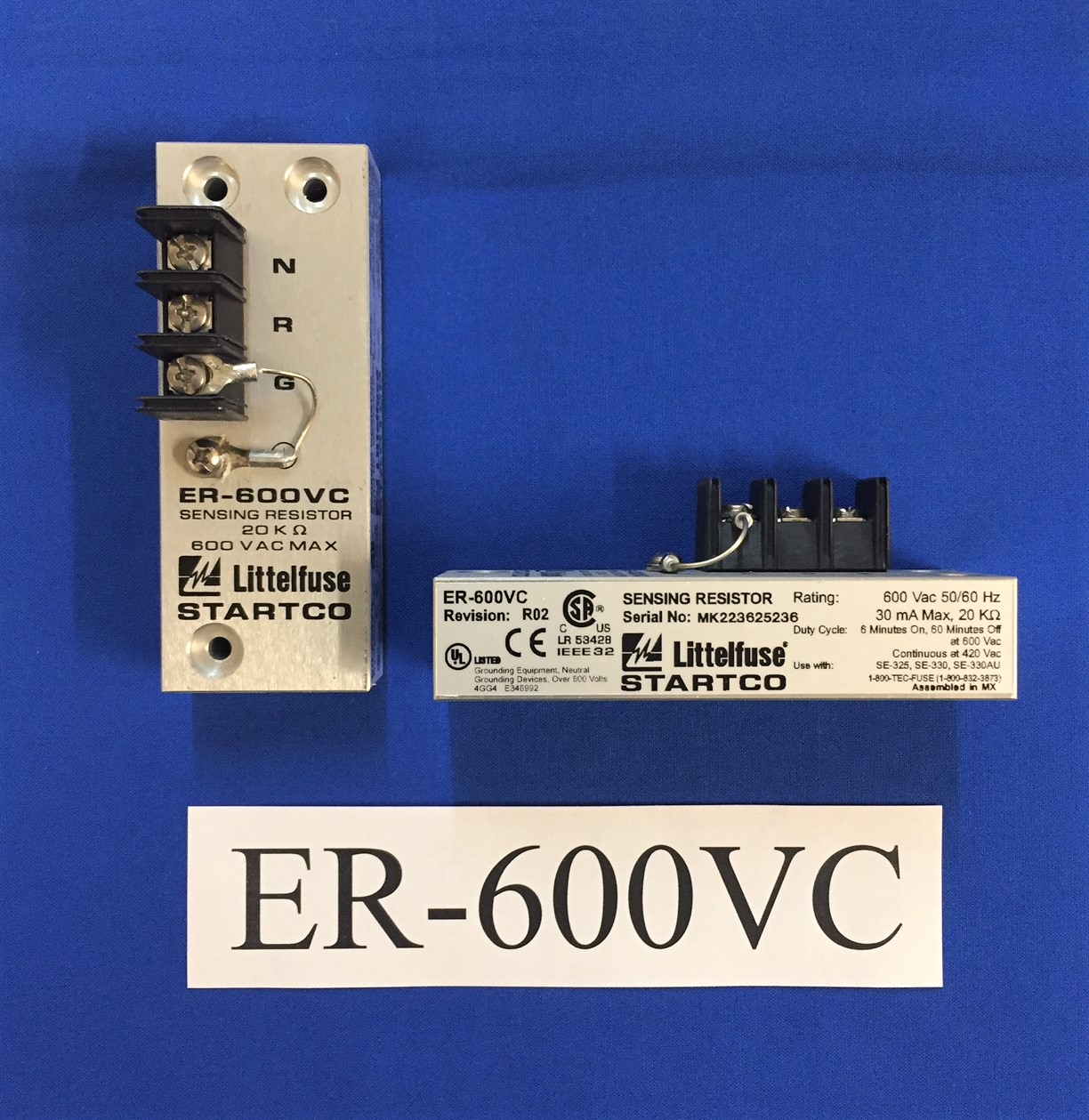
LITTELFUSE STARTCO

Littelfuse Startco Powr-Gard

In 2008 Littelfuse, Inc. purchased Startco Engineering Ltd. The company, which is based in Saskatoon, Saskatchewan, is a recognized leader in ground-fault protection products and custom-power distribution centers that are used in industrial manufacturing and mining applications. Littelfuse acknowledged that the acquisition of Startco will strengthen their position within the industrial protection business and growing mining industry with Startco’s line of ground-fault and motor protection relays.


One of Littelfuse Startco’s main products is the Protection Relay which includes a comprehensive line of motor and pump protection relays, arc-flash relays, ground fault relays, feeder protection, pump controllers, time delay relays, flashers and tower lighting, and more to minimize electrical safety hazards, limit equipment damage, improve productivity, and safeguard personnel from injury due to electrical faults. Professionals in construction, manufacturing, mining, oil & gas, solar, and many more industries rely on Littelfuse Startco for rugged, lasting protection for their designs and critical applications.


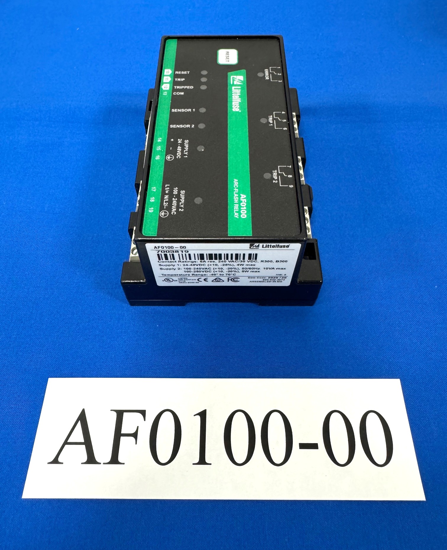
Arc Flash Relays are an effective defense against dangerous arc flash events since they can detect an arc flash in less than 1 millisecond. These relays provide:

  • A redundant internal trip path with two internal trip paths for added reliability
  • Health monitoring which continuously monitors connection to trip coil to ensure path is intact
  • Reliable Light Detection with two types of light sensors (point and fiber-optic) for different application
  • Upstream tripping ability if the local breaker fails to clear the fault
  • Optional current detection for fault verification to avoid nuisance tripping
  • Tie breaker tripping of both incoming feeder and tie breaker when arc is detected
  • Zone tripping give the ability to trip 2 separate zones with 1 relay


Most of Littlefuse Startco’s products are manufactured in Canada with the exception of SE-105, SE-107, and SE-325, which are now manufactured in the United States.

Product Image
Catalog #
Description
Price
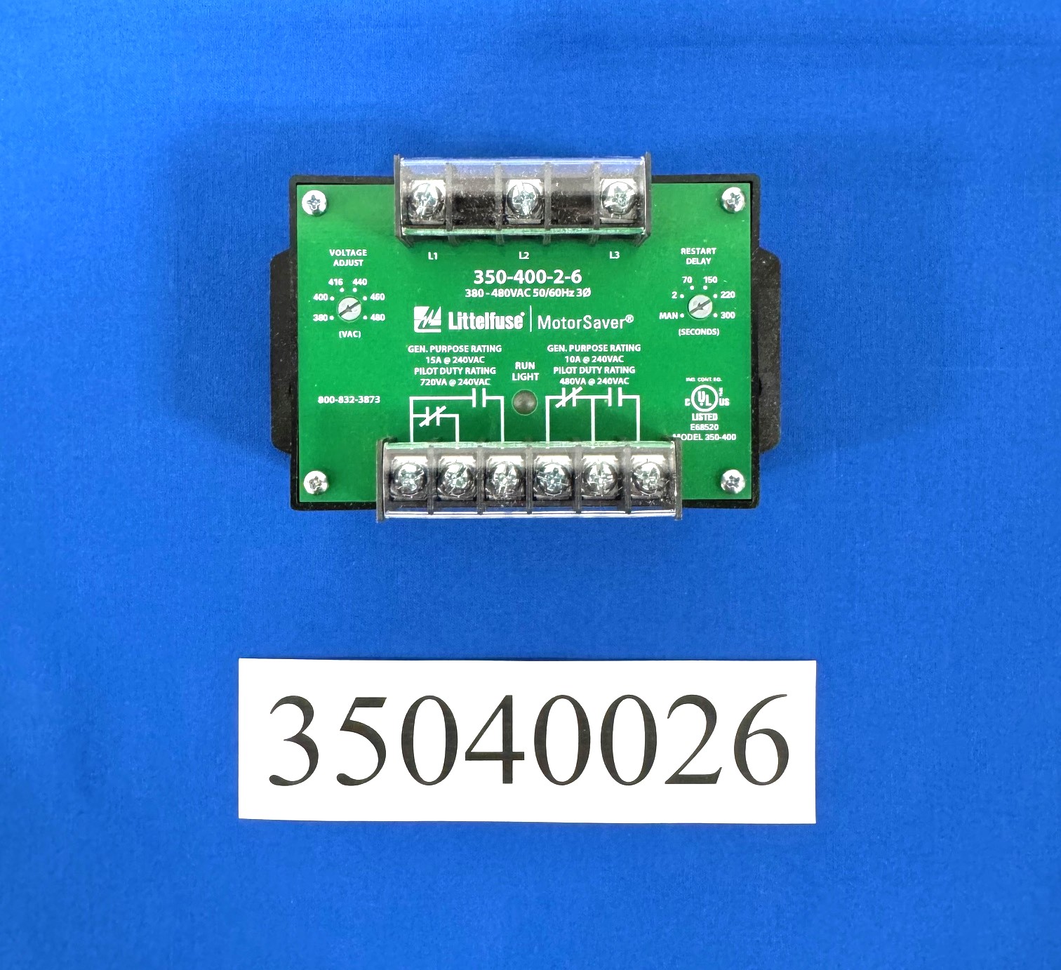
3-PHASE VOLT MON/ 38   Description The 350 series is a heavy-duty voltage monitor. This product should be used when high current relays or dual contacts are required, or 480 V controls are used. Since the 350 series uses heavy-duty relays, it comes in fixed voltage range models rather than a dual auto-ranging version like the model 250. The 350200 has a 15 A general purpose contact. The 350400 provides a SPDT (Form C) relay rated to switch up to 600 V, allowing the use of 480 V controls, eliminating the need for a control power transformer to step the voltage down to 120–240 V. Several DPDT (two Form C contacts) relay models are also available. The 350 microcontroller-based family of products are low cost yet highly advanced solutions to heavy-duty problems. The 350 includes advanced single LED diagnostics. Five different light patterns distinguish faults and normal operating conditions. Other options such as high voltage trip and adjustable restart delay are available. Features & Benefits FEATURES BENEFITS Proprietary microcontroller based circuitry Constantly monitors 3 phase voltage to protect against harmful line conditions, even before the motor is started Advanced LED indication Provides diagnostics which can be used for troubleshooting and to determine relay status Adjustable restart delay (-2 models) settings Allows staggered start up of multiple motors, after a fault, to prevent a low voltage condition 600 V rated relay contacts available on some models Eliminates the need for a control transformer to step voltage down to 120–240 V for a control circui
$304.62
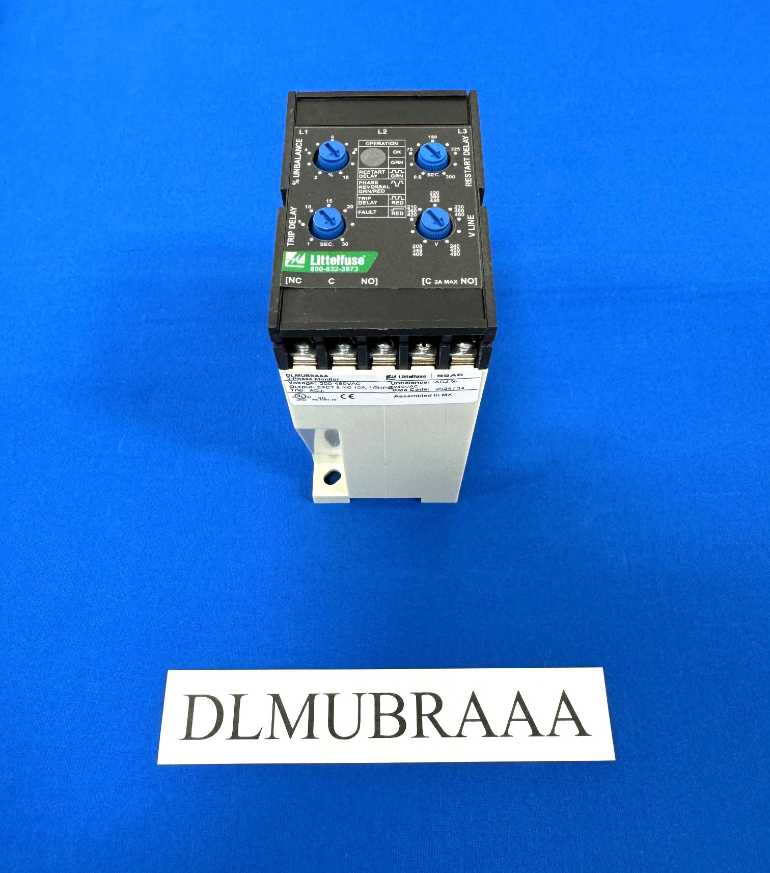
3-PH VOLTAGE MONITOR   Description The DLMU Series is a universal voltage, 3-phase voltage monitor. It continuously measures the voltage of each of the three phases with micro-controller accuracy and compares the value to preset trip points. It separately senses phase reversal and loss; over, under and unbalanced voltages; and over or under frequency. Protection is assured during periods of large average voltage fluctuations or when regenerated voltages are present. The unit trips within 200ms when phase loss is detected. Adjustable time delays are included to prevent nuisance tripping and short cycling of sensitive equipment. The isolated, 10A, SPDT and 2A alarm output relay contacts trip when a phase voltage exceeds the trip limits for the trip delay. Nominal line voltage, voltage unbalance, and time delays are knob adjustable. The phase loss set point and the acceptable frequency range are fixed. Both delta and wye systems can be monitored; no connection to neutral is required. Operation Upon application of line voltage, the output is de-energized and the restart delay begins. If all the 3-phase voltages are within the acceptable range, the output energizes at the end of the restart delay. The micro-controller circuitry automatically senses the voltage range, and selects the correct operating frequency (50 or 60Hz). The over and under voltage trip points are set automatically. When the measured value of any phase voltage exceeds the acceptable range limits (lower or upper) the trip delay begins. At the end of the trip delay the output relay de-energizes. If the phase voltage returns to an acceptable value before the trip delay expires, the trip delay is reset and the output remains energized. Under, over, and unbalanced voltages plus over or under frequency must be sensed for the complete trip delay before the unit trips. The unit trips in 200ms when phase loss or reversal are sensed. The unit will not energize if a fault is sensed as the line voltage is applied. Reset: Reset is automatic upon correction of the voltage or frequency fault or phase sequence
$282.20
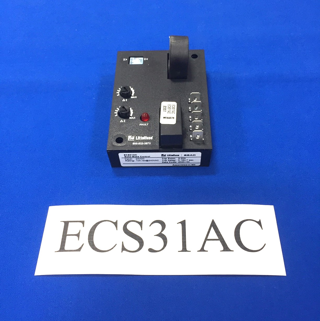
24V CURRENT SENSOR The ECS Series of single-phase AC current sensors is a universal, overcurrent or undercurrent sensing control. Its built-in toroidal sensor eliminates the inconvenience of installing a stand-alone current transformer. Includes onboard adjustments for current sensing mode, trip point, and trip delay. Detects over or undercurrent events like locked rotor, loss of load, an open heater or lamp load, or proves an operation is taking place or has ended. Operation Input voltage must be supplied at all times for proper operation. When a fault is sensed throughout the trip delay, the output relay is energized. When the current returns to the normal run condition or zero, the output and the delay are reset. If a fault is sensed and then corrected before the trip delay is completed, the relay will not energize and the trip delay is reset to zero. Adjustment Select the desired function, over or under current sensing. Set the trip point and trip delay to approximate settings. Apply power to the ECS and the monitored load. Turn adjustment and watch the LED. LED will light; turn slightly in opposite direction until LED is off. Adjustment can be done while connected to the control circuitry if the trip delay is set at maximum. To increase sensitivity, multiple turns may be made through the ECS’s toroidal sensor. The appropriate trip point range is determined by multiplying the amperage load by the number of turns/passes through the toroidal sensor. When using an external CT, select a 2VA, 0-5A output CT rated for the current to be monitored. Select ECS adjustment range 0. Pass one secondary wire lead through the ECS toroid and connect the secondary leads together.  
$149.98
CURRENT SENSOR The ECS Series of single-phase AC current sensors is a universal, overcurrent or undercurrent sensing control. Its built-in toroidal sensor eliminates the inconvenience of installing a stand-alone current transformer. Includes onboard adjustments for current sensing mode, trip point, and trip delay. Detects over or undercurrent events like locked rotor, loss of load, an open heater or lamp load, or proves an operation is taking place or has ended. Operation Input voltage must be supplied at all times for proper operation. When a fault is sensed throughout the trip delay, the output relay is energized. When the current returns to the normal run condition or zero, the output and the delay are reset. If a fault is sensed and then corrected before the trip delay is completed, the relay will not energize and the trip delay is reset to zero. Adjustment Select the desired function, over or under current sensing. Set the trip point and trip delay to approximate settings. Apply power to the ECS and the monitored load. Turn adjustment and watch the LED. LED will light; turn slightly in opposite direction until LED is off. Adjustment can be done while connected to the control circuitry if the trip delay is set at maximum. To increase sensitivity, multiple turns may be made through the ECS’s toroidal sensor. The appropriate trip point range is determined by multiplying the amperage load by the number of turns/passes through the toroidal sensor. When using an external CT, select a 2VA, 0-5A output CT rated for the current to be monitored. Select ECS adjustment range 0. Pass one secondary wire lead through the ECS toroid and connect the secondary leads together.
$152.98
TIME DELAY RELAY 120VAC Description
The ESDR Series offers independent time adjustment of both

delay periods. Adjustment options include fixed, onboard or

external adjust. The ESDR is recommended for air drying,

automatic oiling, life testing, chemical metering and automatic

duty cycling. This series is designed for general purpose

commercial and industrial applications where a small, cost

effective, reliable, solid-state timer is required. The factory

calibration for fixed time delays is <±5%. The repeat accuracy,

under stable conditions, is 0.1% of the selected time delay.

This series is designed for input voltages of 12VDC to 230VAC

in five ranges. Time delays of 0.1 seconds to 1000 minutes are

available in six ranges. The output is rated 1A steady and 10A

inrush. The modules are totally solid state and encapsulated to

protect the electronic circuitry.

Operation (Recycling - ON Time First)

Upon application of input voltage, the output energizes and

the T1, ON time begins. At the end of the ON time, the output

de-energizes and the T2, OFF time begins. At the end of the

OFF time, the output energizes and the cycle repeats as long as

input voltage is applied.

Reset:
Removing input voltage resets the output and time
delays, and returns the sequence to the first delay.

Operation (Recycling - OFF Time First)

Upon application of input voltage, the T2 OFF time begins. At the

end of the OFF time, the output energizes and the T1 ON time

begins. At the end of the ON time, the output de-energizes and

the cycle repeats as long as input voltage is applied.

Reset:
Removing input voltage resets the output and time
delays, and returns the sequence to the first delay
$131.60
KSD3310.1SA
DIGI-TIMER RELAY Description The KSD3 Series Digi-Timer is a cost effective approach for ON/OFF recycling applications. The on time is equal to the off time. An adjustment of the RT will change the time delays of both on and off times. This series is designed for general purpose commercial and industrial applications where a small, cost effective, reliable, solid-state timer is required. The factory calibration for fixed time delays is within 5% of the target time delay. The repeat accuracy, under stable conditions, is 0.5% of the selected time delay. This series is designed for popular AC and DC voltages. Time delays of 0.1 seconds to 1000 minutes are available in 6 ranges. The output is rated 1A steady and 10A inrush. The modules are totally solid state and encapsulated to protect the electronic circuitry.Operation (Recycling Flasher - ON Time First)Upon application of input voltage, the output energizes and the T1, ON time begins. At the end of the ON time, the output de-energizes and the T2 OFF time begins. At the end of the OFF time, the output energizes and the cycle repeats as long as input voltage is applied. Reset: Removing input voltage resets the output and time delays, and returns the sequence to the ON time.Operation (Recycling Flasher - OFF Time First)Upon application of input voltage, the T2 OFF time begins. At the end of the OFF time, the T1 ON time begins and the load energizes. At the end of the ON time the load de-energizes, and the cycle repeats until input voltage is removed.Reset: Removing input voltage resets the output and time delays and the sequence to the OFF time  
$76.79